Imagine a production line grinding to a halt at 2 AM because a digital expansion module throws unexpected faults outputs freezing, inputs misreading, and the entire automated process collapsing into chaos. For technicians working with Siemens micro-PLC systems like the S7-200 series, this scenario is far more common than it should be, and the root causes often trace back to preventable mistakes made during module selection, installation, or configuration.
Siemens digital expansion modules serve as the backbone of scalable automation, allowing engineers to extend the I/O capabilities of compact PLCs without overhauling entire control systems. However, their effectiveness depends entirely on proper handling at every stage from choosing the right module to wiring the last terminal.
This article examines the most frequent errors technicians encounter with Siemens digital expansion modules, provides concrete solutions for each pitfall, and establishes best practices that safeguard system reliability. Whether you’re commissioning a new installation or troubleshooting an existing one, understanding these common mistakes will save you hours of downtime and costly repairs.
Table of Contents
Understanding Siemens Digital Expansion Modules in Automation Systems
Digital expansion modules act as modular building blocks that extend the input and output capacity of Siemens micro-PLCs, most notably the S7-200 series. Rather than replacing an entire controller when a project demands additional I/O points, engineers simply attach expansion modules to the existing CPU via a ribbon bus connector, instantly gaining access to more digital inputs, digital outputs, or a combination of both.
This modular architecture is what makes compact PLC platforms viable for applications that evolve over time packaging lines that add reject stations, conveyor systems that incorporate new sensors, or building management setups that grow zone by zone.
In modern automation systems, these modules handle everything from reading proximity switches and photoelectric sensors to driving solenoid valves and indicator lights. Their reliability directly influences process uptime, product quality, and operator safety.
When a module functions correctly, it operates invisibly in the background; when it fails, the consequences ripple across the entire control system. Because expansion modules sit at the intersection of electrical hardware and programmed logic, errors can originate from multiple directions mechanical, electrical, or software related.
Understanding how these modules integrate with the broader PLC ecosystem is essential before examining the specific mistakes that compromise their performance.
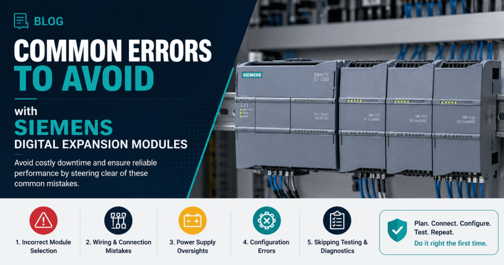
Error #1: Incorrect Selection of Siemens Digital Expansion Modules
One of the most costly mistakes happens before a module is even unboxed. Technicians under time pressure frequently grab a digital expansion module based on a quick glance at I/O count, only to discover during commissioning that it’s incompatible with their CPU model, lacks the correct voltage rating, or simply doesn’t support the signal type their application requires.
Choosing an underspecified module or one designed for a different PLC family—leads to wasted procurement time, project delays, and in some cases, hardware damage when forced connections are attempted.
Factors to Consider for Proper Module Selection
Proper selection starts with confirming compatibility between the expansion module and the specific CPU variant in your system. Not every S7-200 CPU supports the same number of expansion modules, and exceeding the maximum module count will result in unrecognized hardware. Beyond compatibility, you need to match the module’s I/O type to actual field device requirements sourcing versus sinking inputs, relay versus transistor outputs, and the correct operating voltage for your sensors and actuators.
Environmental specifications matter equally: if the module will operate in a cabinet exposed to high ambient temperatures, vibration, or humidity, verify that its rated operating conditions cover those extremes. Finally, consider how the module integrates with your existing I/O addressing scheme to avoid address conflicts that create erratic behavior in your program logic.
Step-by-Step Guide to Selecting the Right Module
Begin by consulting the Siemens S7-200 System Manual, which lists every supported expansion module alongside maximum configuration limits for each CPU model. Next, create a detailed I/O requirements list for your project, specifying signal types, voltage levels, and the total number of points needed—including a reasonable spare capacity of around 10 to 20 percent for future expansion.
Cross-reference your list against the Siemens compatibility charts available in the hardware catalog or the TIA Selection Tool to identify candidate modules. Before full deployment, bench-test the selected module with your CPU by connecting it, powering up the system, and verifying that the PLC recognizes it without errors in the diagnostic buffer. This simple validation step catches selection mismatches before they become field failures.
Error #2: Faulty Installation on DIN Rails for Micro-PLCs
Even when the correct module has been selected, improper physical installation can undermine the entire system before a single line of code executes. Digital expansion modules communicate with the CPU through a bus connector that demands precise mechanical alignment any deviation introduces intermittent connection failures that are notoriously difficult to diagnose.
Technicians who rush through DIN rail mounting often create problems that manifest weeks or months later as random module dropouts, communication errors, or complete loss of expansion I/O during machine operation.
Best Practices for DIN Rail Mounting
Start by inspecting the DIN rail itself for warping, corrosion, or debris that could prevent flat seating. The rail should be a standard 35mm top-hat profile, securely fastened to the panel backplate at intervals no greater than 200mm.
Before snapping the module into place, slide it horizontally toward the adjacent CPU or preceding module until the bus connector engages fully you should feel a distinct click. Verify that the module sits flush against the rail with no rocking or gaps.
Maintain a minimum clearance of 25mm above and below the module for ventilation, and leave at least one slot of space between the last expansion module and any heat-generating components like power supplies or variable frequency drives. Proper cable routing away from the module face prevents mechanical strain on terminals during maintenance access.
Common Installation Mistakes and Solutions
Overtightening terminal screws is a frequent issue—excessive torque cracks the plastic housing or deforms the terminal plate, creating high resistance connections that generate heat and signal errors. Use a torque-limited screwdriver set to the manufacturer’s recommended value.
Misalignment of the bus connector ranks as the most damaging installation error; forcing a module at an angle bends connector pins and causes permanent communication failures.
If a module doesn’t slide smoothly into the adjacent unit, stop and check for obstructions rather than applying force. Environmental exposure also causes premature failure modules installed in cabinets without proper sealing in dusty or humid environments develop condensation on circuit boards.
The solution is straightforward: ensure IP-rated enclosures, install cabinet heaters or ventilation fans where ambient conditions fluctuate, and use protective terminal covers on unused I/O points to block contaminant ingress.
Error #3: Wiring and Configuration Pitfalls with Siemens Components
Wiring and software configuration errors account for a significant share of digital expansion module failures, yet they often go undetected during initial commissioning because the system appears to function normally under light loads.
These problems surface later when production ramps up, electrical noise increases, or edge-case logic conditions trigger unexpected behavior. A single miswired input can cause a safety interlock to misread, while an overlooked configuration parameter can render an entire output group inoperative.
Because wiring and software issues compound each other, addressing both domains systematically is critical to achieving dependable automation performance.
Correct Wiring Techniques for Digital Modules
Every terminal connection should use properly stripped, tinned, or ferrule-crimped wire ends to ensure consistent contact area and prevent stray strands from bridging adjacent terminals. Match wire gauge to the module’s terminal rating undersized conductors create voltage drops that cause false input readings, while oversized wires won’t seat properly in the clamp.
Grounding deserves particular attention: connect the module’s ground terminal directly to the panel’s central ground bus using a dedicated conductor rather than daisy-chaining grounds between modules, which introduces ground loops and noise susceptibility.
Route signal cables separately from power conductors, maintaining at least 100mm of separation where they run in parallel, and use shielded cables for any input wiring that passes near variable frequency drives or high-current switching devices.
After completing all connections, perform a point-by-point continuity and signal integrity check with a multimeter before energizing the system—this five-minute verification catches crossed wires and open circuits that would otherwise require hours of live troubleshooting.
Software Configuration Tips for Automation Systems
Within STEP 7-Micro/WIN or the corresponding Siemens programming environment, confirm that the hardware configuration matches the physical module arrangement exactly modules entered in the wrong slot order will map I/O addresses incorrectly, causing outputs to fire on the wrong channels.
Pay close attention to input filter times: leaving default filter settings when fast-switching sensors are connected results in missed pulses, while setting filters too low in electrically noisy environments produces phantom triggers.
Avoid hardcoding I/O addresses scattered throughout your program; instead, use symbolic addressing with a clearly documented symbol table so that address shifts from adding or removing modules are easy to update globally.
After uploading any configuration change, use the PLC’s built-in diagnostic buffer and module status LEDs to verify that every expansion module reports a healthy state with no configuration mismatch warnings. Running a structured test sequence that cycles each input and output individually before returning the system to production catches programming oversights that static code review alone will miss.
Proactive Measures and Best Practices for Siemens PLC Systems
Preventing expansion module failures requires a shift from reactive troubleshooting to disciplined, ongoing system stewardship. Establish a scheduled maintenance routine that includes visual inspection of bus connectors, terminal tightness checks using calibrated torque tools, and verification of module status LEDs at least quarterly.
Keep firmware current Siemens periodically releases updates that resolve known communication bugs and improve diagnostic capabilities, and applying these during planned shutdowns eliminates vulnerabilities before they cause unscheduled downtime. Maintain a living documentation set that records every module’s part number, slot position, I/O address map, and wiring termination details; this single practice dramatically reduces recovery time when a module must be swapped under pressure.
Invest in technician training that goes beyond initial commissioning—hands-on workshops covering diagnostic buffer interpretation, forced I/O testing, and module hot-swap procedures build the confidence needed to resolve issues quickly. Finally, stock critical spare modules on-site so that a hardware failure doesn’t become a multi-day procurement delay.
Suppliers like Apter Power, known for their expertise in industrial automation components, can help ensure timely access to compatible Siemens components. These proactive habits transform expansion module reliability from a gamble into a predictable outcome.
Safeguarding Siemens Expansion Module Reliability Through Prevention
The three errors explored throughout this article—incorrect module selection, faulty DIN rail installation, and wiring or configuration mistakes—represent the most frequent causes of digital expansion module failures in Siemens S7-200 and other micro-PLC systems.
Each of these pitfalls is entirely preventable when technicians approach their work with the right knowledge and discipline. Selecting a module that matches your CPU’s compatibility requirements, voltage ratings, and environmental conditions eliminates problems before they begin.
Careful physical installation with proper bus connector alignment and adequate spacing ensures reliable communication for the long term. Precise wiring practices combined with thorough software configuration close the gap between a system that merely powers on and one that performs flawlessly under real production demands.
Beyond addressing individual errors, the broader lesson is that expansion module reliability is not accidental—it results from consistent adherence to documented procedures, proactive maintenance schedules, and continuous technician development.
Apply the solutions and best practices outlined here to your next commissioning or troubleshooting task, and you’ll spend far less time chasing intermittent faults and far more time delivering automation systems that run as intended.
Protecting system integrity starts with respecting the details that keep every module communicating, every signal clean, and every output firing exactly when it should.

Pradeep Sharma is a author the mind behind Techjustify, where I craft insightful blogs on technology, digital tools, gaming, AI, and beyond. With years of experience in digital marketing and a passion for tech innovation, I aim to simplify complex topics for readers worldwide.
My mission is to empower individuals with practical knowledge and up-to-date insights, helping them make informed decisions in the ever-evolving digital landscape.